Pixel Perfect outlines for sprites aren’t hard, but for 3D, I’ve been through the darkest corners.
BUT WAIT, you may say, why would it be hard? After all, there are so many articles out there who demonstrate how outline could be done on 3D meshes. Whether it is extruding the normals, screen space edge detection, there got to be an easy way to do this.
Well, I am a little peculiar when it comes to trace outlines. You see, I am not satisfied with the contour; I need hard edges that are inside the contour. Usually, this can be done by sampling the normal map.
But…. I have transparent objects. And they don’t write to screen normals.
This causes 2 problems:
-
Any line drawn based on screen normals but masked by transparent objects is still drawn. Which isn’t visually appealing.
-
Without normals we lose the clarity of outlines on transparent objects. In fact, with how renderers are normally set up, we don’t even have depth. This would result in transparent objects rely solely on color.
Just before we delve deeper, let me explain why I can’t use the normal extrusion method. If you have no idea what that is, we draw an object with vertices extruded in the direction of vertex normals, and give it the color of the outlines. This is basically doing outlines for 2d sprites - sample the original sprite with 1px offset in each direction, effectively extruding the sprite. The method requires smooth and watertight meshes, otherwise it would cause broken looking outlines, which is something I can’t impose based on the game. Also, normal extrusion can’t (afaik) achieve screen space pixel perfectness, which is a significant drawback.
Now, back to our subject.
Edge Detect
When I first started, I used the method that I am most familiar with: Edge detection. I stumbled across an article that uses Roberts kernel on depth and normal map, which has a problem at acute viewing angles since that causes depth value to change dramatically. The author compensated that by using the screen normals - the more perpendicular the screen normal is to the view vector, the less weight should be put on the normal value.
I implemented the Roberts kernel, but also a Laplacien kernel, which I use more often in computer vision projects. The result is interesting, as the Laplacien kernel does not have the acute viewing angle artifacts that are present when using Roberts kernel. Aside from that, there’s no significant difference in outline quality. The Laplacien kernel is heavier though, because it is a 3x3 kernel while Roberts is 2x2. However, considering we don’t need to apply view angle adjustments and we are in low resolution, I’d say it is a gain.
Here I am only showing Laplacien, as I have deleted everything about Roberts from my shader.
Laplacien Edge Detect:
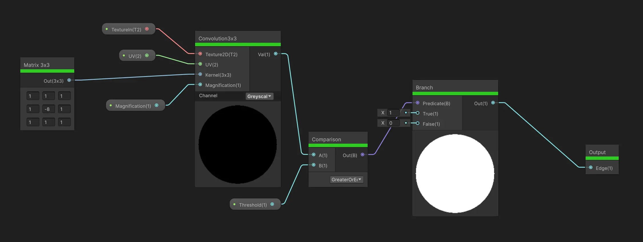
This post explains the building blocks of this convolution node.
Edge detection on normals texture comes with a natural problem when we are in low resolution though, when we detect a sudden change in value, two color channels are affected, with a displacement of 1px. This is not prominent in high resolution, but in low resolution, 2px is easily told apart from 1px. I haven’t come up with a way to solve this but perhaps later.
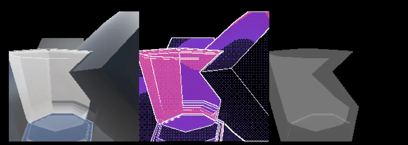
Anyway I did this for color, depth and screen normals.
Retrieve Depth and Screen Normals (Shader Graph)
Depth is straightforward, we need the SceneDepth node. But since it takes UV and outputs depth value directly, we can’t use the same graphs as with the color texture. Feasible but tedious.
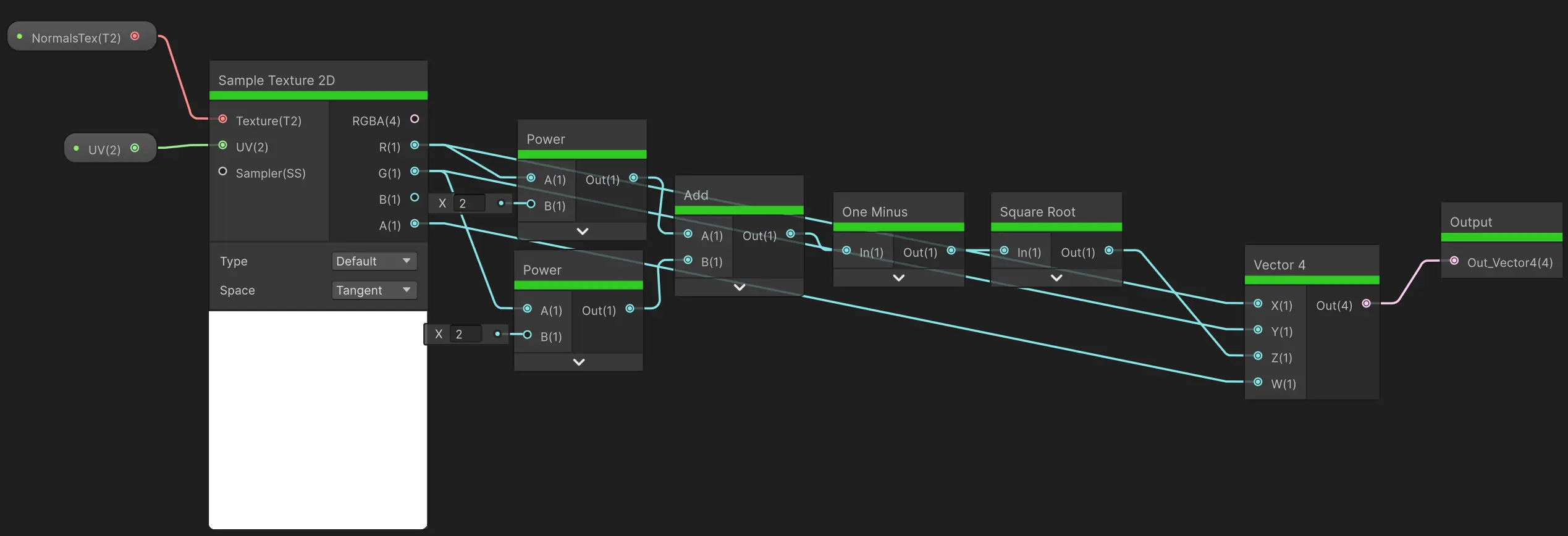
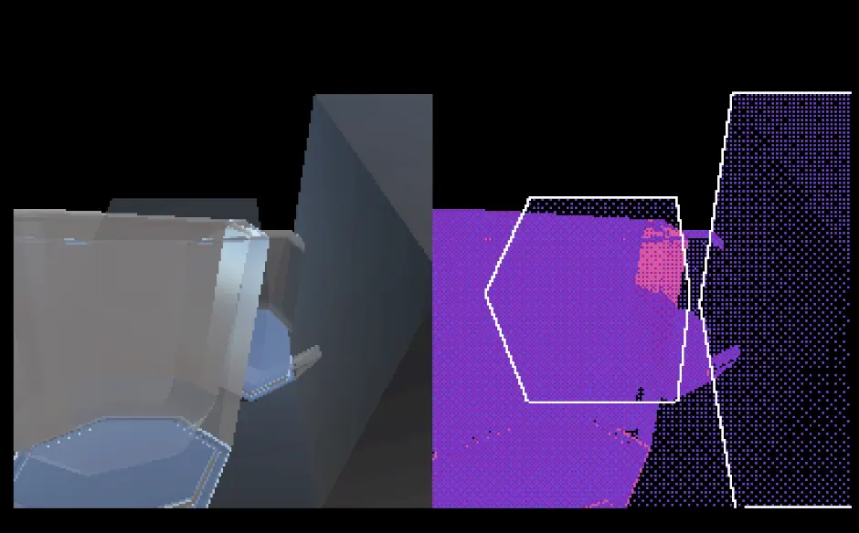
For normals, we need the name of a global variable, which is _CameraNormalsTexture. Create a Texture2D variable and name it CameraNormalsTexture, set the scope to Global, and ticking off Show In Inspector.
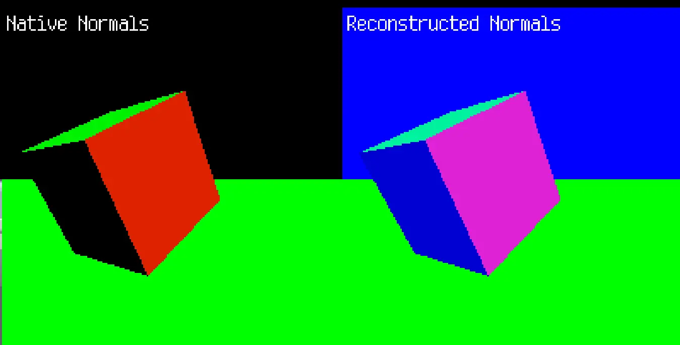
It can now be sampled as any other texture, but here’s a trap: Unity stores normal vectors as Vector2 (r,g) instead of Vector3 (r,g,b). This is because normal vector is a unit vector ( magnitude = 1 ), thus it has only 2 degrees of freedom. The third component of a normal vector can be calculated with the 2 known by using Pythagorean Theorem.
Note on Depth and Screen Normals Texture
The shader I am developing was previously a full-screen effect. Later I discovered that I only need to render 3D objects in a more constrained area of the screen, thus it is turned in to an effect that applies to 2D textures. I still conserved the ability to apply it full-screen though, as a matter of fact, it is just the difference between using _MainTex or _CameraSortingLayerTexture.
But what about depth and screen normals? Turned out that these two, if I render the result to a render texture, will have size equal to that render texture. And if we don’t have other things that write to depth and screen normals in different size, they will always remain of that size.
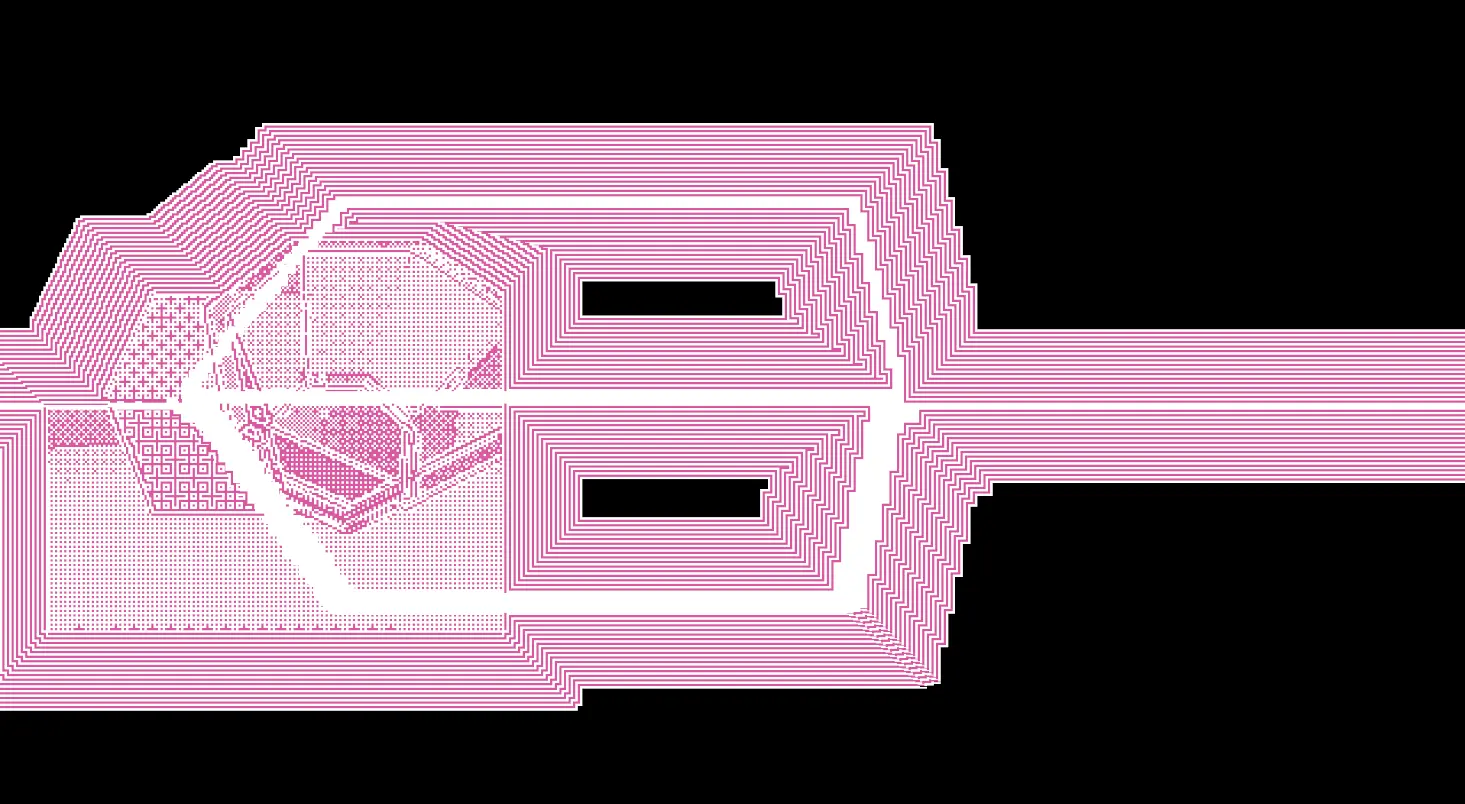
This is what happens if we render the 3D objects to a 200x200 render texture while enabling depth and normals based outline, using the “full screen” mode of the shader:
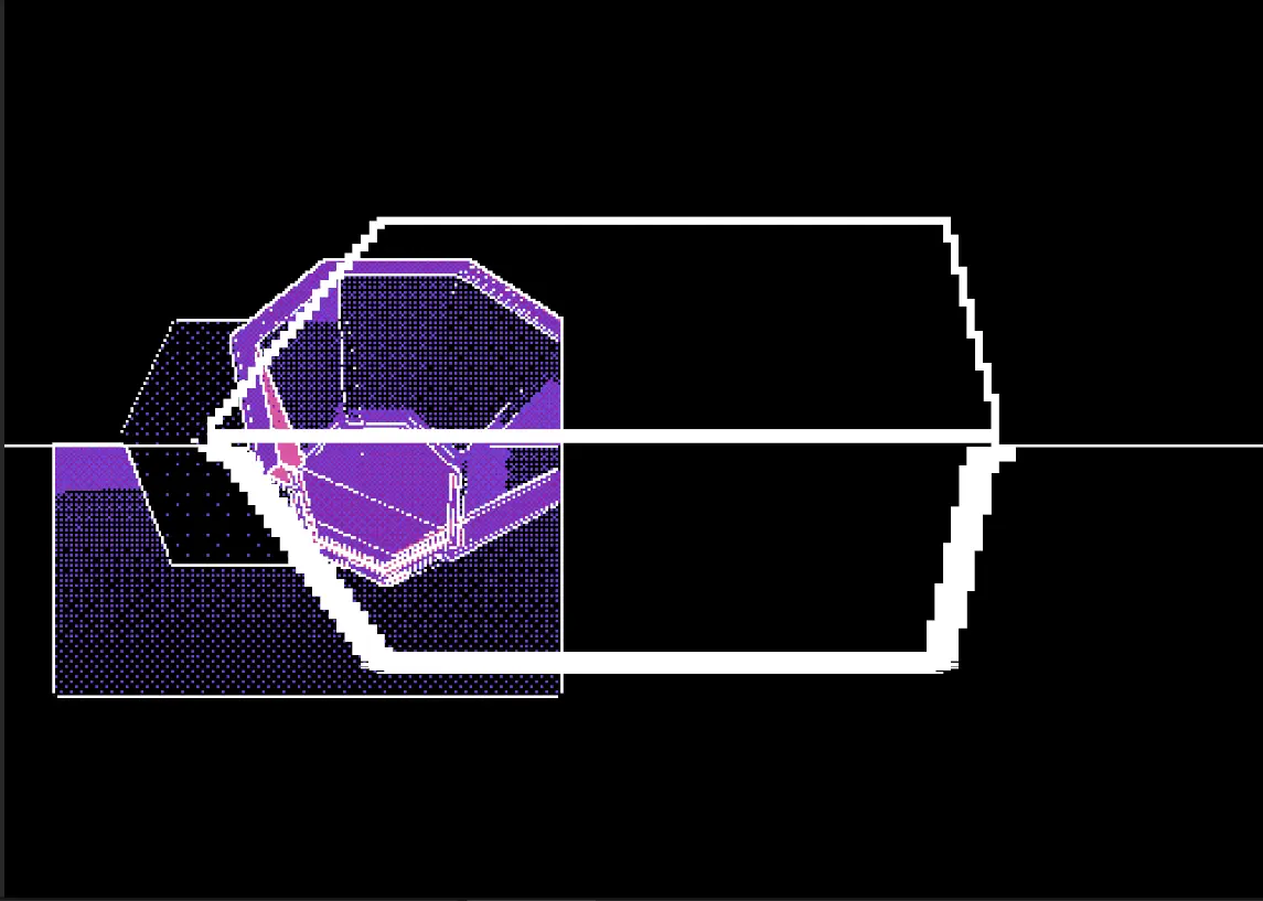
We can see that only the color based contours are correct, because the screen color texture is of the correct size, but depth and normals based contours are like stretching a 200x200 texture to full screen.
Intermezzo: Camera Sorting Layer Texture
I write this because a funny problem has occurred to me twice, each time I have no idea what is happening in the first 10 minutes.
This is simply due to the fact that the shader using the camera sorting layer texture renders to it as well.
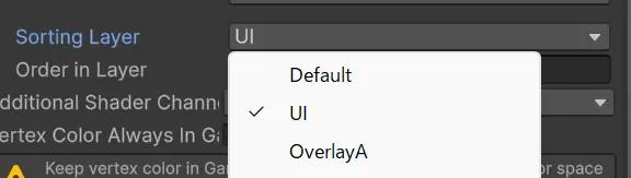
For example, this is the canvas containing a shader that uses the camera sorting layer texture.
And in the URP settings, the foremost camera sorting layer texture is UI.
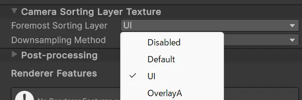
The solution is therefore to make sure everything using the camera sorting layer texture should be put in the layer above the foremost sorting layer texture. In this case, OverlayA.
Transparent Objects
Now here is a sort of like untraveled hinterland, because not much attempt has been made on drawing contours/structure lines on transparent objects.
The difficulty, as I have explained earlier, is that transparent objects don’t write to depth and screen normals by default. It is, however, possible to force write to depth buffer.
Default (transparent objects don’t write to depth buffer)
Write Depth with Less comparison
It looks… fine. But there’s reason why transparent object don’t write to scene depth by default.
Here is a scene where a transparent object is not in front of the cube which looks correct - we are only seeing the cube
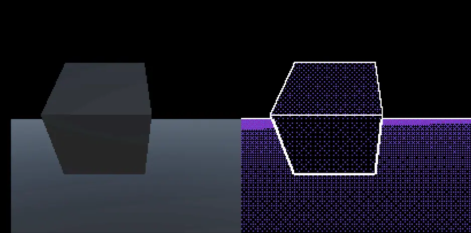
Now if we take another transparent object in front of the cube, miracle happens, the transparent object behind the cube is showing up…
As I tested many other options, there is no depth write option that ensures a correct perspective under all circumstances.
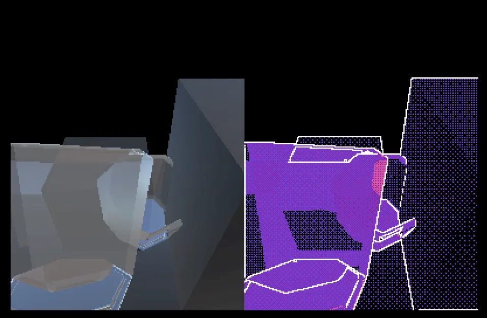
My current approach, unfortunately, is to rely only on color for transparent objects. It looks OK, with the only problem that contours that should be obscured by transparent objects are showing through.
What if… we are able to mark all pixels that are affected by transparent objects?
My first attempt was to add another camera that renders transparent objects only, to a render texture. But that doesn’t work, as we are not able to detect any opaque objects in front of transparent objects. And the ordering of the renderer is strange, if below normal 3D renderer it would clear depth and normals texture, and if above, it clears color.
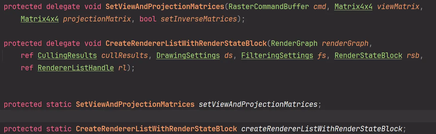
After days struggling with URP’s internal access modifiers, I finally did it:
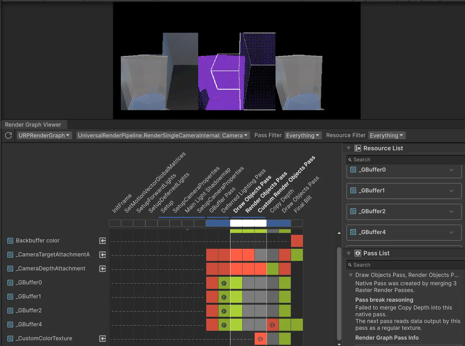
I’ve created a global texture called _CustomColorTexture that can be accessed from shaders, and the Custom Render Objects Pass renders objects to that texture (only color, we still use depth texture form main camera, but since transparent objects don’t write depth, it is effectively read-only).
It isn’t magic though, I simply copied the built-in RenderObjectsPass, fix access modifier problems with cached reflections, and replaced render attachment with the self-allocated render texture (allocating with RTHandles.Alloc(...) and import with renderGraph.ImportTexture(...) ).
Bind to global shader variable is done by using builder.SetGlobalTextureAfterPass(...).
Unity is shifting towards Render Graph, a technology with currently very poor documentation. I just hope my code still works after the release of Unity 6… I might try to write something about it later.
Please Unity, be open (public)
NOTE: And indeed, one of them became publicly accessible in Unity 6.
With this obstacle cleared the rest should be relatively simple.
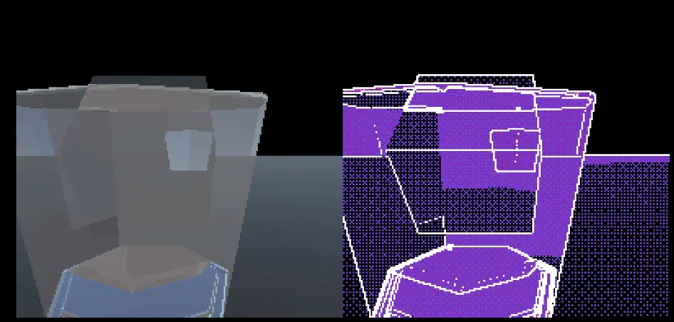
The contour lines obscured by transparent objects are no longer showing through.
Finale
I end this article here because I think all the necessary puzzle pieces are in place. With these we can easily enhance the quality of transparent object’s outline using the custom color texture, dither the contour line based on how many layers of transparent objects are in front of that object, and other refinements if required.
IMPORTANT UPDATE
Past Unity 6000.0.5f1, _CameraNormalsTexture no longer works as intended. This is because GBuffers are no longer global.

I temporarily solved it by adding a pass after deferred lighting that copies GBuffer2 to a persistent texture. Now think of it, I should just declare using the GBuffer2 and then the Render Graph will solve this issue for me.