In this fourth part, we will finally add vertex displacement to the grass’s vertex shader. We will use shader graph - which should make things a touch easier. But most important logic will be put inside a custom function node which should make it easier to include for readers that prefer a pure code approach.
Pendulum Library
Before diving into the vertex shader straight away, let’s create a pendulum library. Recall what we have established in part one:
The 3 cases for grass motion \(\theta(t)\) are:
- Underdamped : \(\theta(t)=\theta_0*e^{-\gamma t}cos(\omega t)\)
- Overdamped: \(\theta(t)= e^{-\gamma t}(A_1e^{\omega t}+A_2e^{-\omega t})\) where \(A_1 = \frac{\theta_0}{2} + \frac{\gamma\theta_0}{2\omega}\) and \(A_2 = \frac{\theta_0}{2} - \frac{\gamma\theta_0}{2\omega}\)
- Critically damped: \(\theta(t) = \theta_0(1+\gamma t)e^{-\gamma t}\)
With:
- \(\gamma=\frac{b}{2*l_0}\)
- \(\omega_0 = \sqrt{\frac{g-k}{l_0}}\)
- \(\omega = \sqrt{abs(\gamma^2-\omega_0^2)}\)
The implementation is straightforward, with some cached computations here and there. We are using half precision because we don’t really need single precision for this computation (I’ve tested both; they aren’t noticeably different).
Create a Pendulum.hlsl file and type/copy-paste the following code:
#pragma once

/* Physical simulation of damped pendulums.
 * * All formulae use "small angle approximation" ( sin(x) = x ) even for big angles.
 * Which means it is not strictly correct but should be visually correct. */
#define PENDULUM_GRAVITY 9.8

half pendulum_omega_zero_sqr(half pendulumLen, half elasticity)
{
    return (elasticity + PENDULUM_GRAVITY)/pendulumLen;
}

half pendulum_gamma(half dampingCoef, half pendulumLen)
{
    return 0.5*dampingCoef/pendulumLen;
}

half pendulum_omega(half elasticity, half pendulumLen, half gamma)
{
    return sqrt(max(0,pendulum_omega_zero_sqr(pendulumLen, elasticity) - gamma*gamma));
}

/* In all cases, we assume initial conditions for f(t) -> θ:
 *  -  f(0) = θ0 (initial angle) *  -  f'(0) = 0 (no initial angular velocity) */
half pendulum_underdamped(half initialAngle, half t, half elasticity, half pendulumLen, half dampingCoef)
{
    half gamma = pendulum_gamma(dampingCoef, pendulumLen);
    return initialAngle*exp(-t*gamma)*cos(pendulum_omega(elasticity,pendulumLen,gamma)*t);
}


half pendulum_critically_damped(half initialAngle, half t, half elasticity, half pendulumLen, half dampingCoef)
{
    half gamma = pendulum_gamma(dampingCoef, pendulumLen);
    return initialAngle * (1 + gamma * t) * exp(-t*gamma);
}


half pendulum_overdamped(half initialAngle, half t, half elasticity, half pendulumLen, half dampingCoef)
{
    half gamma = pendulum_gamma(dampingCoef, pendulumLen);
    half omega0 = pendulum_omega_zero_sqr(pendulumLen, elasticity);
    half r = sqrt( abs(gamma * gamma - omega0 * omega0) ) ;
    half r1 = - gamma + r;
    half r2 = - gamma - r;
    half rdiff = r1 - r2;
    half a = -initialAngle * r2 / rdiff;
    half b = initialAngle * (1 + r1 / rdiff);
    return a*exp(r1*t) + b*exp(r2*t);
}
Current Angle and Displacement
We will now sample the texture we filled in the last part. The texture provides initial angle and elapsed time for our motion equation. We still need elasticity, pendulum length, and damping factor. These will be passed into our vertex displace function and are exposed in the inspector.
Create PlantVertexDisplace.hlsl and start with the following:
#include "Pendulum.hlsl"

/* osParams layout
 * x: min os y pos (anchor) * y: max os y pos * z: * w:
 */
void PlantVertexDisplace_float(
    in float3 osPos,
    in float3 wsPos,
    in float4 osParams,
    in float dampingCoef,
    in float elasticity,
    in float4 influenceTex,
    in float trample,
    out float3 osDisplacement,
    out float trampleStr
)
{
    half angle = 0;
    half initialAngle = length(influenceTex.xy);
    half t = influenceTex.w;
    half pendulumLen = osParams.y - osParams.x;
    #if _PENDULUM_CRITICALLY_DAMPED
    angle = pendulum_critically_damped(initialAngle, t, elasticity, pendulumLen, dampingCoef);
    #elif _PENDULUM_OVERDAMPED
    angle = pendulum_overdamped(initialAngle, t, elasticity, pendulumLen, dampingCoef);
    #elif _PENDULUM_UNDERDAMPED
    angle = pendulum_underdamped(initialAngle, t, elasticity, pendulumLen, dampingCoef);
    #endif
}
Some explanations of the parameters:
osPosis the vertex’s Object Space position.wsPosis the object’s World Space position - not the world space position of the vertex. I have tried the latter, and it looked horrible. (You could try it yourself)osParam, thexcomponent is the object’s root in object space, andyis the object’s highest point in object space. (float4 is actually an overshot, you could just use float2)influenceTexis the sampled influence texture’s color value.trampleis the trample strength multiplier. We will discuss this later.osDisplacementis the object space displacement vector.trampleStris the resulting trample strength, again, discussed later.
Physically speaking, the equation we should use is determined by the constants, but here we leave the choice to the artist instead - as they probably just want the grass to behave in a particular way by clicking a button, without thinking about how the constants should be adjusted to achieve that look. And to be honest, most of the time you would just want the under-damped case. If that’s true, then you could remove the two other cases.
Optionally, you could make pendulum length a standalone exposed constant for even more artistic control (while being less physically correct).
We have the current angle now. The next thing is to turn it into a displacement vector. To do this, we need to rotate the grass blade by the current angle. The axis of this rotation is perpendicular to the plane containing the grass blade and the direction vector (the normalized rg channel of the influence texture).
Here’s a diagram illustrating this rotation:
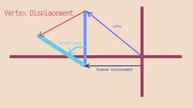
Note that we are not rotating osPos directly, as the root of the object may not be where the object space position is zero. Therefore, we account for the plannar displacement of the grass blade (displacement in xz plane relative to object space origin), and the height of the root configured via osParams.x.
Let’s prepare for the rotation:
float3 directionVect = normalize(float3(dir.x, 0.001, dir.y));
float3 rotationAxis = cross(directionVect, float3(0,1,0));
rotationAxis.y = max(rotationAxis.y, 0.001);
rotationAxis = normalize(rotationAxis);
float3 planarDisplacement = float3(osPos.x, 0, osPos.z);
float3 grassBlade = osPos - planarDisplacement;
There are plenty of small values here, because we don’t want normalization to end up with a zero division. And when they do, the grass simply won’t render.
For the rotation itself, we will use Rodrigue’s Rotation Formula:
The formula is given by:
\[\mathbf{v}_{\text{rot}} = \mathbf{v} \cos \theta + (\mathbf{k} \times \mathbf{v}) \sin \theta + \mathbf{k} (\mathbf{k} \cdot \mathbf{v}) (1 - \cos \theta)\]Where:
- \(\mathbf{v}\) is the original vector to be rotated.
- \(\mathbf{k}\) is the unit vector along the axis of rotation.
- \(\theta\) is the angle of rotation.
- \(\mathbf{v}_{\text{rot}}\) is the resulting rotated vector.
// Rodrigue rotation
float3 afterRot = grassBlade * cos(angle) + cross(rotationAxis, grassBlade)* sin(angle) + rotationAxis*dot(rotationAxis,grassBlade)*(1-cos(angle));
The osDisplacement is simply:
osDisplacement = grassBlade - afterRot;

// for now, set trample strength to 0
trampleStr = 0;
NOTE: In “standard” implementation of interactive grass, you would typically find multiplying the displacement by either
uv.yor normalized height of the vertex. This is unnecessary in this implementation, as the rotation itself already accounts for the “closer to root, less displacement” effect.
This should be enough for setting up our interactive grass. Let’s create a grass shader to see it in action!
The Grass Shader
Properties
Create a Lit Shader Graph, and add these properties to the blackboard:
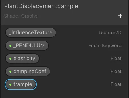
The Scope of _InfluenceTexture must be set to Global so that it correctly references the global texture we set in EIR custom pass.
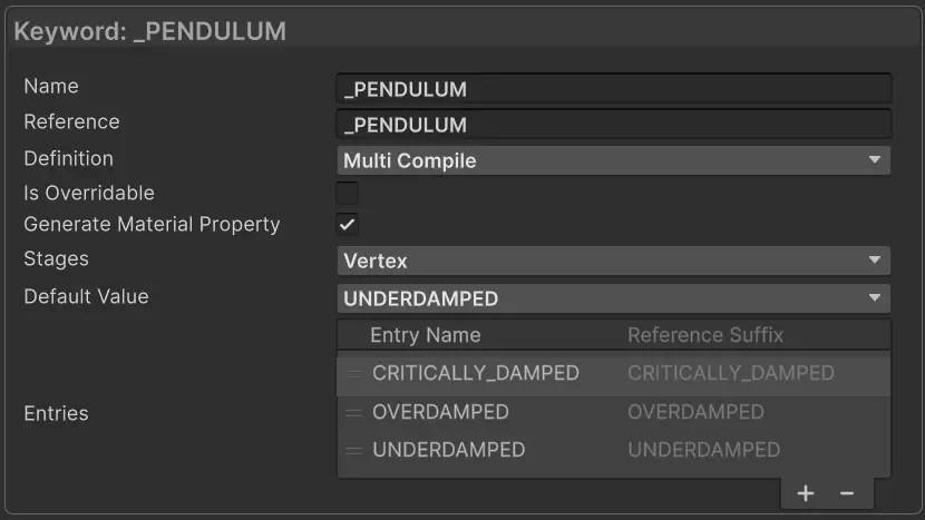
The _Pendulum enum is set as follows:
NOTE: Some values are not yet exposed since this is a test shader - particularly
osParams. You should definitely expose it later.
Plant Vertex Displace custom function
To use the function we created earlier, we will need to use a Custom Function node. But it is usually better to create a Sub Shader Graph for it so that you could drop it in another shader with no need to create all the ins and outs. (You could always copy-paste it, though, but I find creating sub shader graphs easier to manage.)
The process of creating this sub shader graph is tedious, but here it is…
It’s literally just a wrapper around a custom function node.
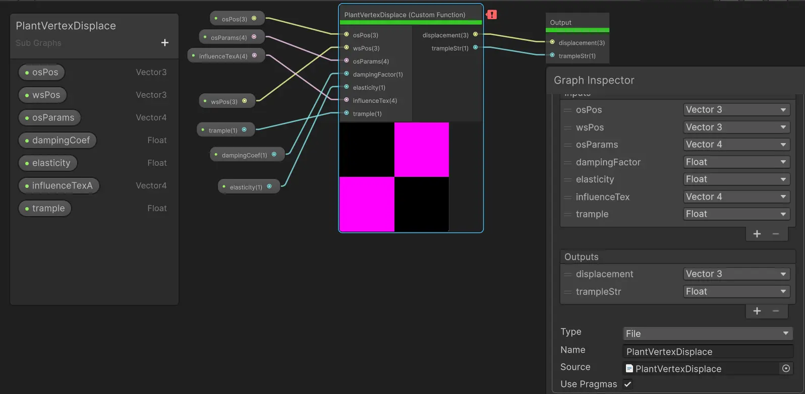
There’s a warning about not having a half precision method. You could ignore it since we will use a single precision shader graph, anyway.
Sample Influence Texture
Back to the lit shader graph. The first thing we need to do is to sample the influence texture. Here we need to convert a world position to uv, and the correct formula for it is:
\[uv = (worldPos.xz - worldOrigin.xz)/worldSize\]worldSize and worldOrigin should actually be read from global floats. I’m cutting some corners here by hard-coding the world size into the shader graph. If you have multiple maps that vary in size, then don’t copy me!
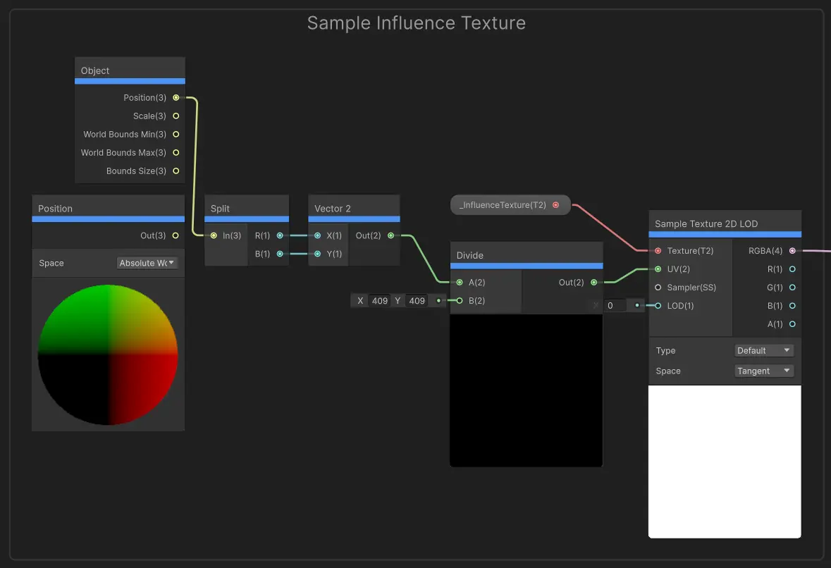
The Position node here is a legacy of trial-and-error. I used to take vertex position as wsPos but it turned out horribly by having crazy deformations, therefore I changed it to an Object node so that the whole object samples with the same uv, giving a more consistent result.
Wire Up Plant Vertex Displace
There’s not much to explain here, except for the hard-coded osParams.
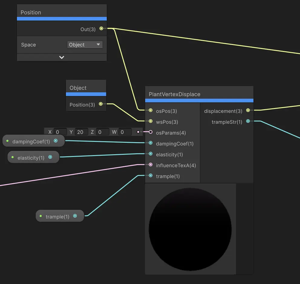
NOTE: Well, I notice I named a parameter
InfluenceTexAhere. This is again a legacy naming. I used to have 2 influence textures before I figured out how to pack everything into one texture.
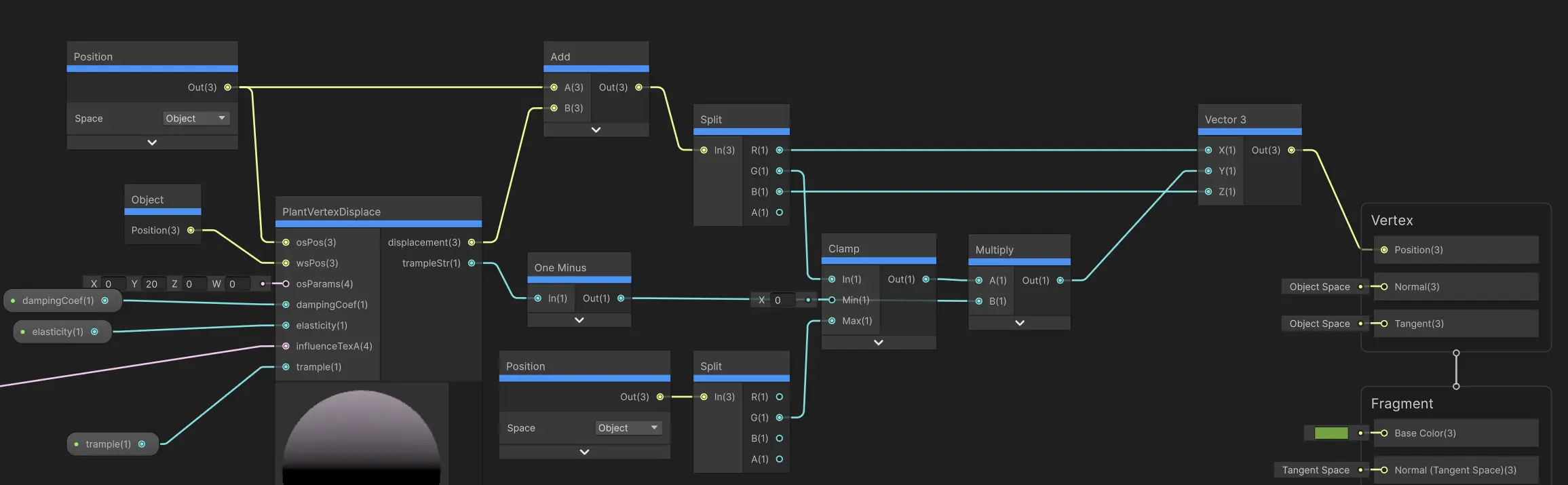
Final Vertex Position
Finally, we could compute the vertex position (object space). This should simply be vertex’s object space position plus the displacement. But here, we limit the height of the resulting position so that it never exceeds the original height (more of a precaution).
Testing
Alright, now you could create a material and put it on your grass. If you don’t have any… you could create a Tree with 3D Object / Tree.
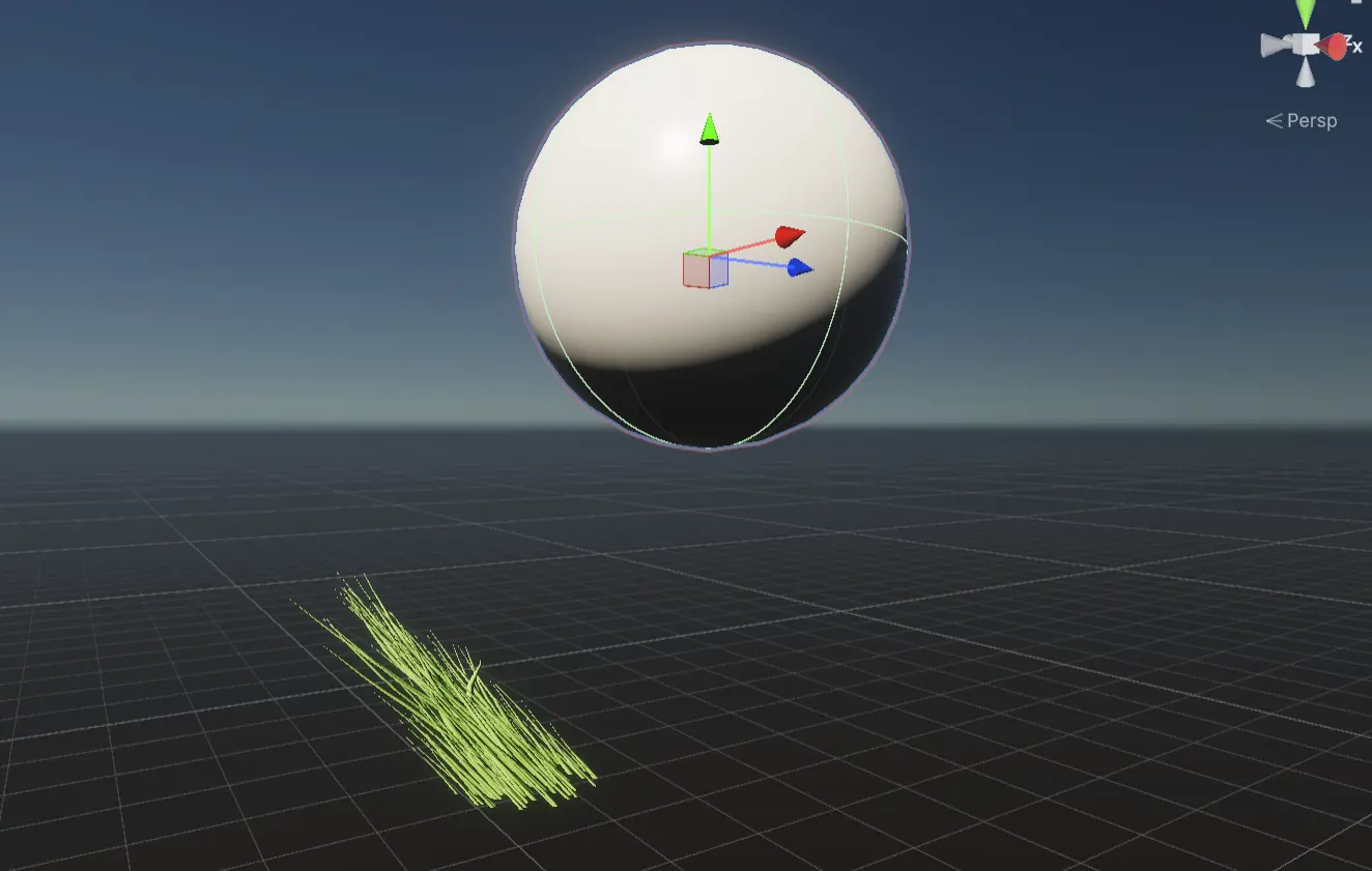
Next, create an object with EntityInfluenceProvide, set its radius and height accordingly. The following example shows an object with radius 25 and height 5.
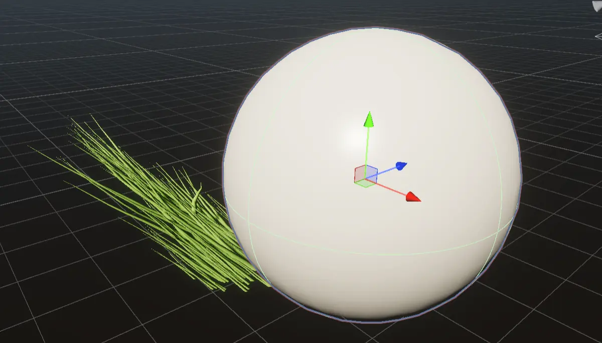
Drag around the object and play with the constants to see the interaction in action. You might need to enter play mode to see it smoothly.
Entity Elevation
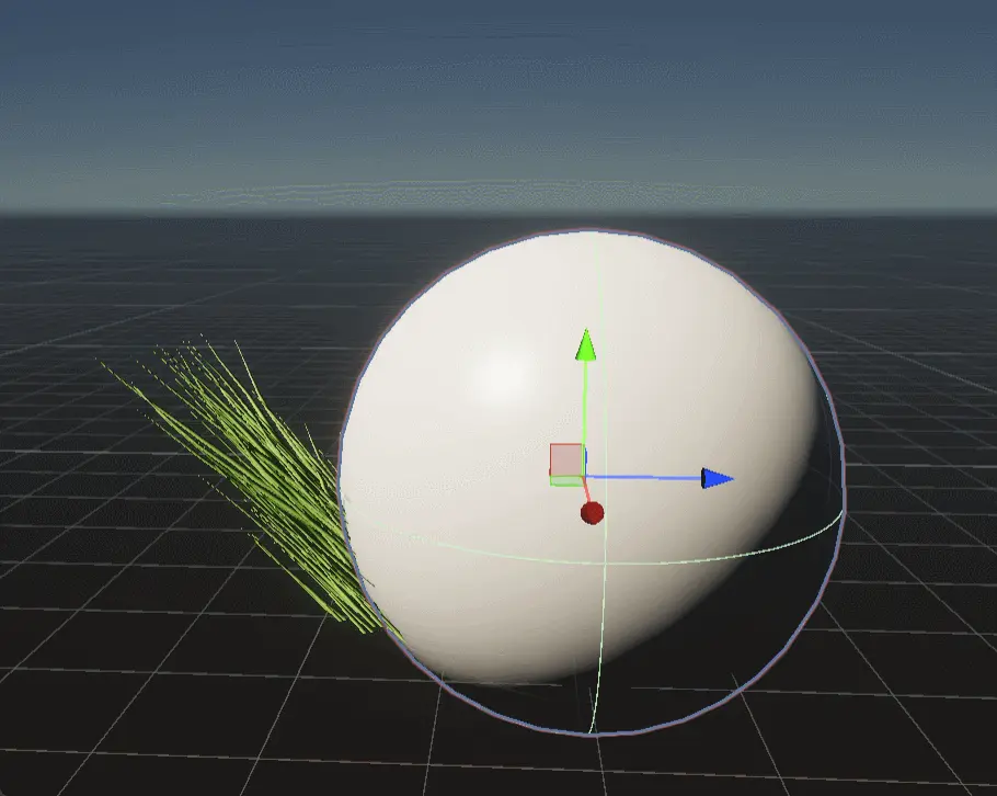
The previous test shows we are ignoring the elevation of the entity:
And indeed… we haven’t used the elevation we calculated in EIR custom pass yet. Let’s fix it now.
The idea is to convert the entity’s elevation to something comparable to the grass blade’s height. The following lines show an normalization approach:
float entityElevation = influenceTex.z;
// determine press strength (reduce strength when the object is above the grass)
float rawStr = 1 - (entityElevation - wsPos.y)/max(0.1,osParams.y - osParams.x);
float str = smoothstep(0.5, 1, rawStr);
And then, after calculating the rotation, we multiply the result by str:
osDisplacement *= str;
This solution is still simplistic and doesn’t account for other cases, for example, when the entity is below the grass. But this is only relevant if you have underground sections.
Trample
Trample effect primarily considers the distance between the grass blade and the entity - the closer the entity is, the stronger our trample effect. However, we do not have this distance yet, and we do not have extra channels to store the distance in our texture. We could, of course, add another texture, but performance-wise that would be terrible. So instead, we could guess this distance from initialAngle.
We know initialAngle is clamped between 0 and 90 degrees, and when it is 0, the grass is upright, unaffected by any entity. Also, the function that gives initialAngle is a strictly decreasing function between 0 and entity radius, and for a given entity, it only depends on the distance between the entity and the pixel, therefore we could safely use it to estimate the distance:
float dist = initialAngle/HALF_PI;
trampleStr = saturate(saturate(str) *  saturate(1 - dist) * trample * (1 - saturate(t)));
OK there’s actually a lot more going on here.
str: this is the same as entity elevation’s impact. If the entity is high-up then we do not apply any trample.1 - dist: distance between the entity and the grass blade.trample: exposed constant for fine tuning.1 - saturate(t): reduce trample over time.
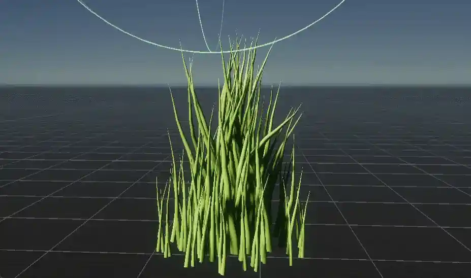
The added lines produce a result like this:
Rotation and Scale
One final problem we need to solve is that we have ignored the grass blade’s transform rotation. For example, this is when the grass has 180 degrees rotation around the y axis:
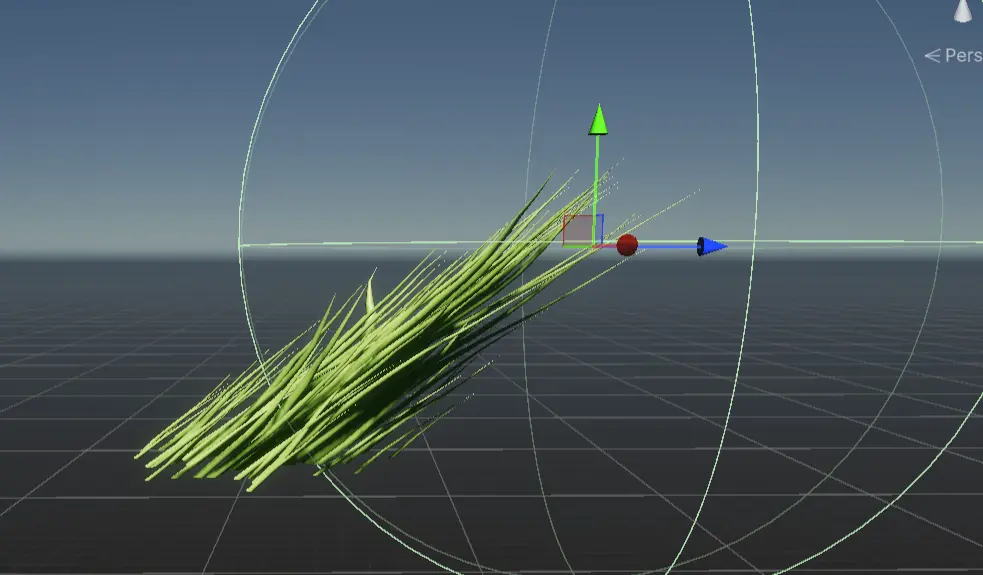
It is defying the rules of physics by leaning towards the entity.
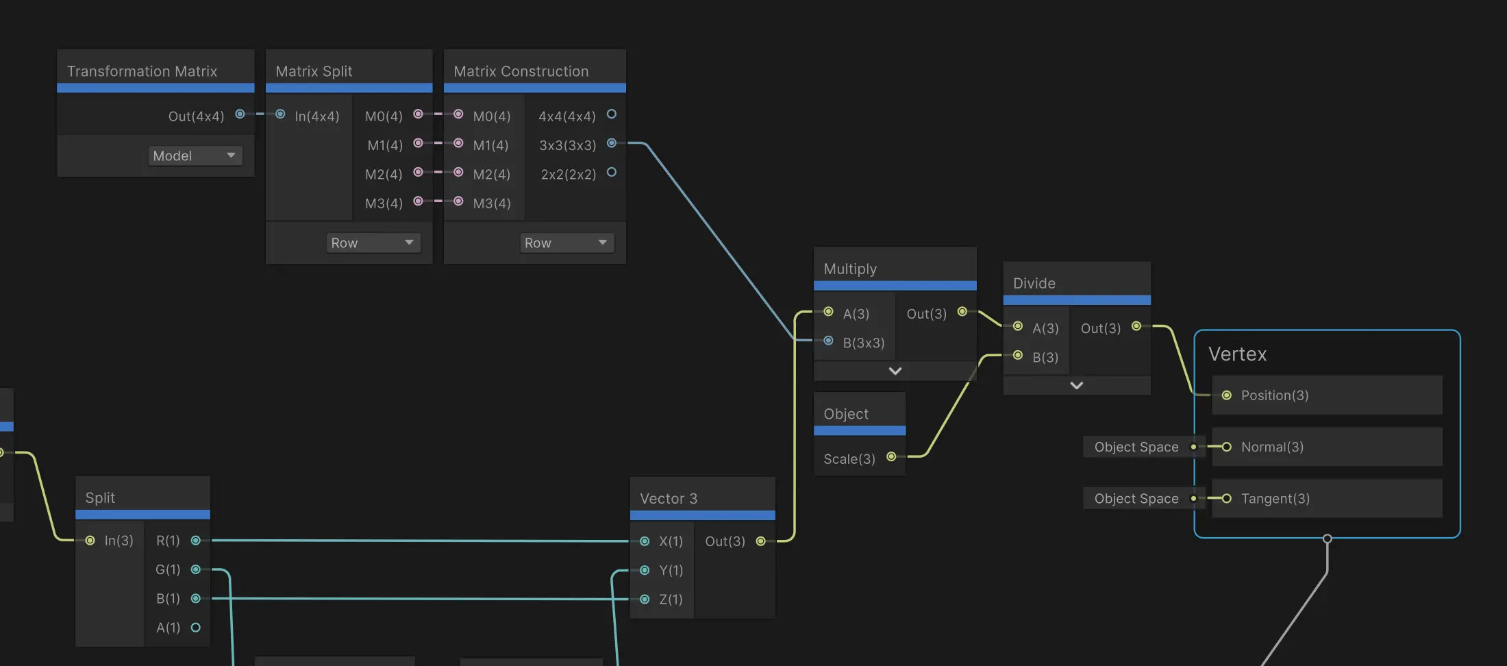
The solution is simple yet slightly weird in shader graph: multiplying the final vertex position by a rotation matrix. This rotation matrix is part of the model matrix of the grass blade, and we will take the upper-left 3x3 of it, which actually gives rotation and scale transformation. After that, we divide the result by the object’s scale or else the scale is applied twice:
Recap
This should provide a good enough base for everything. Feel free to adjust any of the calculations.
Here’s the vertex displacement function so far:
#include "Pendulum.hlsl"
#define HALF_PI 1.5707963

void PlantVertexDisplace_float(
    in float3 osPos,
    in float3 wsPos,
    in float4 osParams,
    in float dampingCoef,
    in float elasticity,
    in float4 influenceTex,
    in float trample,
    out float3 osDisplacement,
    out float trampleStr
)
{
    half angle = 0;
    half initialAngle = length(influenceTex.xy);
    half t = influenceTex.w;
    half pendulumLen = osParams.y - osParams.x;
    #if _PENDULUM_CRITICALLY_DAMPED
    angle = pendulum_critically_damped(initialAngle, t, elasticity, pendulumLen, dampingCoef);
    #elif _PENDULUM_OVERDAMPED
    angle = pendulum_overdamped(initialAngle, t, elasticity, pendulumLen, dampingCoef);
    #elif _PENDULUM_UNDERDAMPED
    angle = pendulum_underdamped(initialAngle, t, elasticity, pendulumLen, dampingCoef);
    #endif
    osDisplacement = 0;
    trampleStr = 0;
    osPos.y -= osParams.x;
    half2 dir = initialAngle > 0.0001 ? influenceTex.xy/initialAngle : half2(0,0);
    float entityElevation = influenceTex.z;
    // determine press strength (reduce strength when the object is above the grass)
    float rawStr = 1 - (entityElevation - wsPos.y)/max(0.1,osParams.y - osParams.x);
    float str = smoothstep(0.5, 1, rawStr);

    float3 directionVect = normalize(float3(dir.x, 0.001, dir.y));
    float3 rotationAxis = cross(directionVect, float3(0,1,0));
    rotationAxis.y = max(rotationAxis.y, 0.001);
    rotationAxis = normalize(rotationAxis);
    float3 planarDisplacement = float3(osPos.x, 0, osPos.z);
    float3 grassBlade = osPos - planarDisplacement;
    /* Instead of lateral displacement, we use rotation.
     * Rotation can better preserve the shape of the grass.     */    // Rodrigue rotation    float3 afterRot = grassBlade * cos(angle) + cross(rotationAxis, grassBlade)* sin(angle) + rotationAxis*dot(rotationAxis,grassBlade)*(1-cos(angle));

    osDisplacement = (grassBlade - afterRot);
    osDisplacement *= str;

    float dist = initialAngle/HALF_PI;
    trampleStr = saturate(saturate(str) *  saturate(1 - dist) * trample * (1 - saturate(t)));
}
In the next and final part we will address some other issue and performance concerns.