This is an effect I have been doing a lot in 2D, but in 3D it adds many complications, notably the plane of slash is no longer a flat plane and it varies a lot depending on the animation, which caused my usual method of using a pre-made mesh + shader + vfx to render the trail unusable.
With a little digging, I found a method to create the effect in 3D. But I have to say this method is not at all simple and took me 3 days of research to achieve the result.
In fact, in this method, (which I believe should be the same method used in the classic asset X Weapon Trail by watching the presentation video), you will create the mesh in runtime, and apply a material to render it). Most of the hard work really is in the part of creating a mesh, and I will explain why it can cause a headache.
Mesh Generation
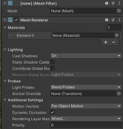
Introducing the two most important components: Mesh Filter and Mesh Renderer. Mesh Filter is actually very simple, it keeps a reference to a mesh and allows the mesh renderer to render the mesh. The Mesh Renderer keeps information about rendering details (notably the material). With these two components set up, it is possible to assign a mesh created at runtime to the Mesh Filter (MeshFilter.mesh) and get it rendered.
However, there is a little twist.
When I first try this method, I created the two components in edit mode and reference them in my script. The object (I call it Trail Object), is a child of the weapon. This will create strange results, since render result will be originated from the Mesh Filter’s position, plus any rotation applied to it. To avoid such complications, it is better to create the object in Start and leave it in the root hierarchy (parent to nothing). Since it is in Start, the overhead can be ignored.
Now, to construct the mesh, we start with something easy. A mesh should at least contain 2 basic informations: Vertices, an array of Vector3, and Triangles (sometimes called Indices), an array of int. If you don’t already know, the computer only draws triangles (so if you have a rectangle, the computer draws 2 triangles). Vertex (singular for Vertices), is the point on the corners of a triangle, and an Index (singular for Indices), is a way to tell the renderer how to draw the vertices (how should the triangle be constructed from the vertices).
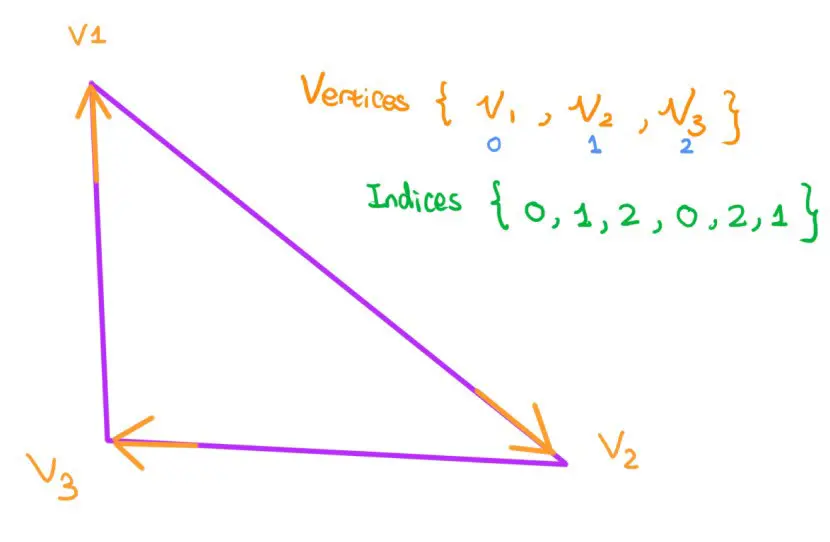
Observe the example here above. If your Vertices contain {V1, V2, V3}, to draw a triangle following the order V1=>V2=>V3, you would put {0,1,2} in your Indices array. The number in indices array corresponds to the vertex’s index number in Vertices array.
For each triangle, you need 3 vertices to signify their corners, and actually 6 indices to correctly draw the triangle. This is because if you only draw your triangle in one order, your triangle will be single-sided. That means when the camera is not facing the triangle’s normal (vector perpendicular to the triangle’s plane), the triangle will not be rendered. The direction of the triangle is dependent according to which order you draw your triangle. So, in our case, to make the triangle visible in any angle, the triangle should be drawn in both clockwise and counter-clockwise.
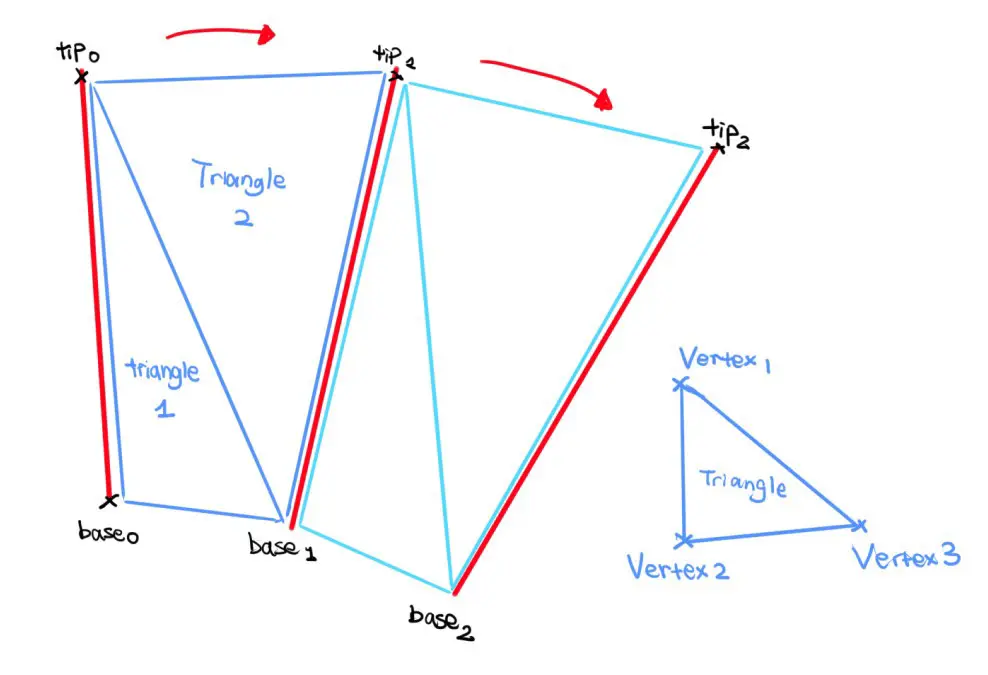
With that in mind, we can start working on our mesh. We will assume the weapon is a straight sword, and the blade can be described with two points: base and tip. I call the segment formed by base and tip stem. For each frame, base and tip will be updated by animation, and if we keep track of the history positions, we should have a list of stems. By connecting adjacent tips and bases, we will have a zig zag plane that describes the trail of the weapon. Now, since each pair of adjacent stems contains 4 vertices, we should draw 4 triangles (2 unique shapes * 2 directions to ensure that the mesh is double sided), that means 12 indices for each pair.
For now, it is relatively easy to implement. You will also need to define a maximum frame length so that when a stem’s life exceeds this limit, it is discarded and replaced by a fresh stem (this looks like a Queue, but I did it manually with a List since it is easier to iterate). By defining this maximum frame length, you can also more easily allocate the space needed for arrays.
Interpolation
You may quickly find a problem: If an action is so quick that the two adjacent stems are far away from each other, your trail will not look good (sharp edges). To solve this, and this is also the hardest part, you will need to apply for an Interpolation Algorithm. What Interpolation means is that the algorithm generates stems to fill in the gaps between the two adjacent stems. And the generated stems will be positioned so that the edge is a curve instead of a straight line. I found an article that discuss some of the mechanism behind X Weapon Trail, and in the article, the Interpolation used is Catmull-Rom.
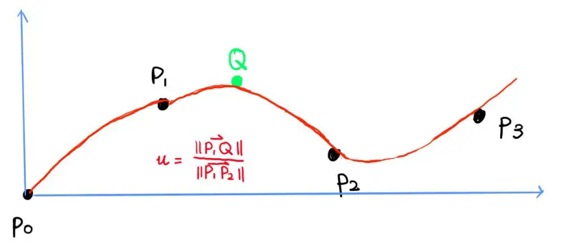
A Catmull-Rom spline requires 4 points (P) to produce the interpolated point (Q) - 2 points prior to the interpolated point and 2 points after the interpolated point. It also requires a parameter u (in some reference, t ), which represents how far in the curve the interpolated point is. This can be defined by the proportion between the distance P1Q and P1P2 as shown above. The calculation is defined by a matrix multiplication:
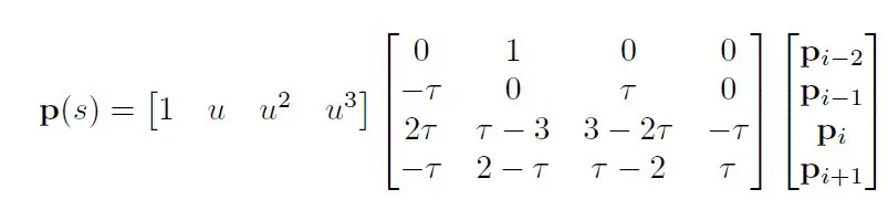
The tau value is called the tension of the curve, which directly affects how the resulting curve looks like. The value is normally 0.5.
You may notice that P in the above function is a vector (it is bold). And since matrix multiplication is linear, you can apply this function to each component of the vector (x, y and z) to produce the resulting component.
So you should be good to translate the function to code. The only possible issue is how would you produce the u value ?
A possible solution is that you don’t care about the actual position of the stems. You only use them to interpolate points. Your actual mesh will be separated by evenly spaced interpolated points:
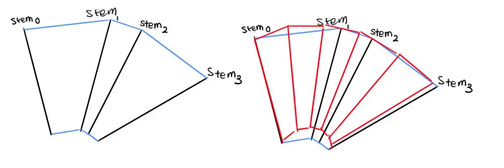
You define u before finding which 4 points should be used for interpolation. If you know the total length of your mesh (preferably the length of the zig-zag curve created by the middle points of the stems), you can divide this length by a user defined integer (resolution of the mesh) to have the spacing between each interpolated stem. Note that the step is not yet the parameter u. To demonstrate how the parameter u can be found, consider the following example:
For instance, the fourth interpolated stem (red) has a distance of 3x step to the beginning of the mesh (stem0). Visually, this interpolated stem should be interpolated by using stem0, stem1, stem2 and stem3, and the value u is given by:
\[( 3*step - dist( stem1 , stem0 ) ) / dist( stem2 , stem1 )\]Where dist() gives the distance between the two stems.
So what you end up with is to find the stem P1, which should be the closest stem on the left (closer to the start of the mesh). By closest, you can define as the distance between the mid-points of the stems. If you keep a record of the stems’ distance to the first stem (the final one will contain the total length of your mesh), you can just iterate through the list and find the stem P1. And there you go you should have all the parameters needed for Catmull Spline.
Applying Material
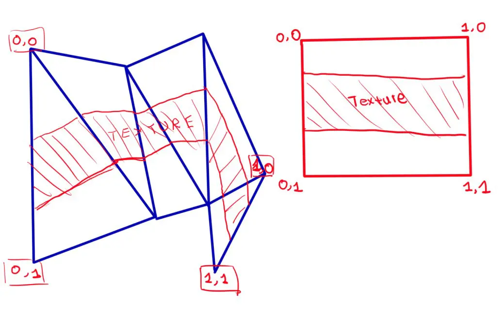
If you did all the above correctly, you should have something that works. But what about material? Well, you will need to specify the UV coordinates of the vertices.
UV tells the renderer how to map the texture on your mesh, and it is an array of Vector2. Each vertex will have its own UV value. UV coordinates should be clamped between 0 and 1, with (0,0) the top left corner and (1,1) the bottom right corner. In our case, you need to know the distance between two adjacent tip or base vertices and the total length of your mesh, and you can calculate the relative proportion and use that as UV’s horizontal value. For vertical, it is just 0 and 1 since the stem should cover the total vertical length.
With all these settled, it is possible to create a powerful weapon trail plugin, but surely it demands dedication… I am still thinking about whether it can be fun to support extremely curved swords (which will need extra points to define the blade), or even whips (that can be diabolical).